
ACME 4-tube Reflex
Broadcast Receiver (1924)
Curiosity got the best of me when I
first saw this circuit. I've
only built one Reflex receiver in the past and it was a relatively
simple 1-tube set using a 3A8GT. I like the idea of reflexing to
make one tube do multiple functions but the old timers will tell you
straight up that the technique has its share of problems and
quirks. Well, thats all I needed to hear as MORE incentive to
take on this challenging project.
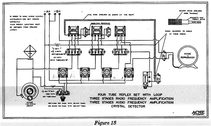
This fella works as follows:
V1. RF amp Stage #1
V2. RF amp Stage #2, later
reflexed as an audio amp stage
V3. RF amp Stage #3, later
reflexed as an audio amp stage
Crystal Detector, then back to V2
V2. Audio amp
V3. Audio amp
V4. Audio amp
to speaker or phones
See schematic
for more detail.
I started parts shopping with the Acme
4-tuber in mind. All I had
was an ACME tuning cap in the junkbox. I drifted away to some
other projects and lo-and-behold a 4-tube homebrew version popped up on
ebay at a very good price. ($36, only 2 bidders - that speaks for the
condition it was in - that breadboard below fetched ~ $500 !!!).
It was indeed a "parts set" but provided most of what I needed for my
project. No, I didn't butcher up a perfectly good piece of
vintage equipment - somebody beat me to that by chopping out parts and
attempting to convert it to a simple TRF set - but I can't call it a
restoration OR a homebrew. Its somewhere in between. How
about restoration of somebody else's homebrew that had been modified?
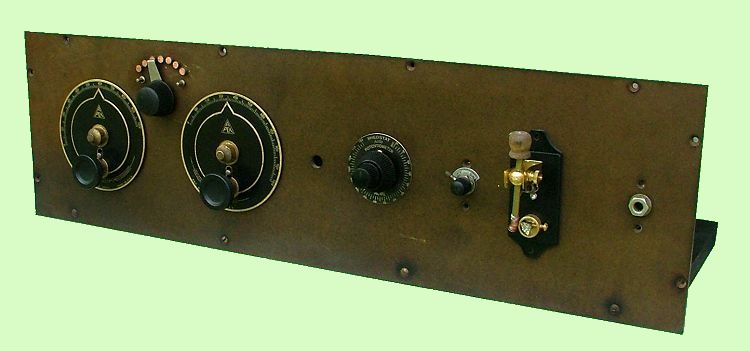
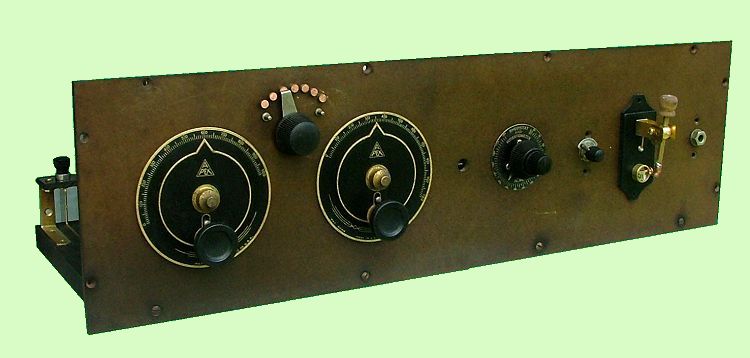
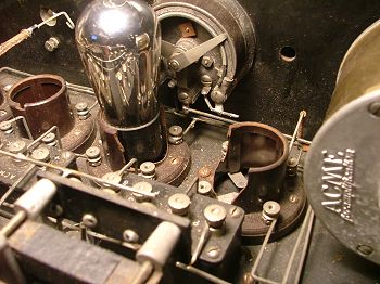 Here's the one I
got. Not bad
but not good either. Broken sockets, missing parts, faded front
panel. Parts set.
Here's the one I
got. Not bad
but not good either. Broken sockets, missing parts, faded front
panel. Parts set.
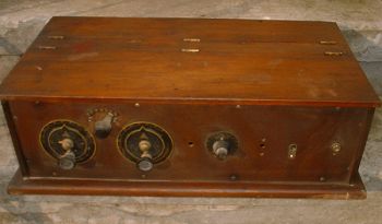
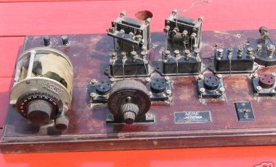
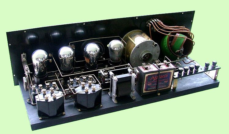
Here's
a nice breadboard version of the set that recently sold on ebay (not
mine).
Before finding my set I had embarked
on making my own replicas of the
ACME RF Transformers. I understood that Acme staggered the center
frequency for the R-2, R-3 and R-4. This is partly due to their
inability in those days to make a good flat RF transformer. I
found with a piece of ferrite rod I could wind a pretty doggone flat
one but as I learned afterwards that may well not have worked in this
circuit. Part of Acme's insight was to stagger the rf gain
distribution as well and my "better" xfmr may not have allowed
this. I could probably have flattened them more with added
resistance across the windings and in the process knocked off some of
the gain. That should work but once I had the actual parts
there's was no reason to re-invent that wheel.
Just to give an idea of how staggered
the R-2, 3 and 4 are, here's a
chart of the measured inductances. Not only are the frequencies
staggered but the ratios seem to be as well.
| R-2 |
Pri
|
300 uH
|
R-2
|
Sec
|
550 uH
|
R-3
|
Pri
|
3000 uH
|
R-3
|
Sec
|
4200 uH
|
R-4
|
Pri
|
830 uH
|
R-4
|
Sec
|
2150 uH
|
My set had an open R-2. No
biggie, these Acme xfmrs are fairly
easy to repair. I previously had bought a 'dud' R-2 from PTOP to
learn about the innards so I was ready for this.
My set also had two replacement AMRAD
xfmrs and doggone it one of them
was open. I restuffed it with a cheapo 2.5:1 modern xfmr.
One of the quandries I faced regarding the audio transformers was which
one could be expected to be the best load for my crystal detector since
each of the three were different. I opted to use the single
remaining original Acme one figuring the result couldn't be any worse
than original. If I were to do this from scratch I think I'd go
with a high ratio here (T1), something like a 6:1. I used my
cheapo restuffed one for coupling the final audio stage.
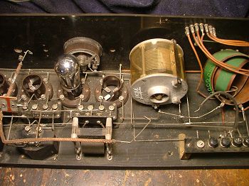
So here's the project close to
completion:
I
guess that faded black panel doesn't look TOO bad in brown.
The set took right off and worked the
first time I fired it up. I
used a modern glass diode for the detector while waiting on parts to
build a 'rock' detector. It was immediately more than I expected
out of the set. A few issues though:
1) Overload by my local station
on 1370. I finally built an
inline trap which I have needed for my projects and that worked
wonders. My Acme is using a tapped variocoupler instead of the
recommended loop antenna so I am somewhat selectivity challenged. After
all, its only a single-tuned circuit. Once its all tweaked out and at
the right regeneration point its plenty selective on the bottom 3/4 of
the band.
2) Tuning range. The
original builder used a generic
variocoupler and its not the best combination for the 500pf Acme tuning
cap. Range was about 480-1400 kc. I removed a couple of
turns but it didn't move appreciably. Removing more would involve
some butchering of the coil so I left it be.
3) Dual pot/rheo. The Acme
info that I have doesn't spell
out exactly which of their dual pot/rheo models is to be used in this
circuit. The one found in place had a 30 ohm rheostat which
suggests the original guy used 99s (although 01As were in the
sockets). Maybe he didn't know better. I got one from PTOP
with a 6 ohm rheostat. But...the 30-ohmmer had 200 ohms for the
pot section, the 6-ohmmer has 100 ohms. Again, not specified by
Acme but it would seem higher would be better since its a load directly
across the A terminals to pick off bias. I'm not running off of a
battery so I guess its moot. Some of the Acmes use a 2k pot
across one of the rf xfmrs as a 'volume' control. Thats not the
case here. The little Acme layout diagram isn't very clear about the
connections and I had no schematic. The pot/rheo has some
internal connections which must be noted.
First tests were running the set with
about 100v B+. I tried the
3v C battery both at the end of the pot and on the wiper with differing
effects. First point of confusion was the wiring of the pot
itself but after I sorted that out I was able to drop the B+ current
draw from the hungry 30-35ma range down to 22ma which seems more
appropriate for a 4-tube set.
The bigger surprise came when I
lowered the B+ to 70 volts. I noticed
when I switched off the radio that I got a burst of volume. So I
dropped the B+ down to about 70 volts and got better performance and a
current of only 11ma!
Then I took out the 3v battery and
tried 45v drawing 16ma and still
sounds good, better than at 100 v.
Filament control behaves a little
smoother as well. It drops dead
below 3.5 volts but I seem to get my best/cleanest volume right around
3.8v. Before it was taking the max on the rheostat.
One suggestion made to me was to set
it up for 90v on the last tube
which is audio only and maybe run everything else at 45. That
might be
the best of both worlds. I think it would also be worthwhile to
add a filament rheostat for the audio stage alone since the other one
is somewhat consequential in the regeneration and performance of the
radio. I don't think I can make those changes now in my set but
if the reader is building from scratch he'd be well advised to consider
that option. For mine I have decided that 4.5 volts of C-voltage
and something around 80 volts B+ seems to a good compromise.
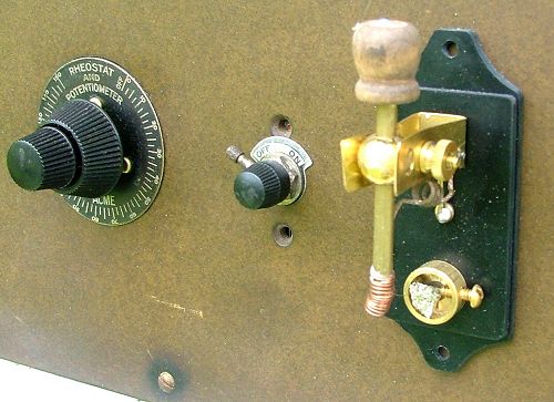
The crystal detector was missing from
my set so that was something else I had to improvise. It had
originally used a Brownlie panel mounted type and I'm not able to find
a replacement. So for the meantime I cobbled together the one
shown made with some parts sold as an ebay item. That item had so
inherent shortcomings so I added a direct jumper from the shaft of the
ticker to the connection point using a flexible coil of phosphor-bronze
dial cord. I also added a strand from that same dial cord to
serve as the actual tickler instead of depending on copper wire for
that purpose. It works quite well and is not at all tedious to
find an active spot on the crystal.
Bill Meacham
- August 2006

