I had been interested in building a "1920s style" shortwave superhet
but info is scarce on such models since use of short waves was still
not widespread. I came across an article in June 1930 QST which
detailled converting a by-then-obsolete Crosley Bandbox into a
superhet. The text made mention of the original article by Ross
Hull in March 1929 QST and later by L.W. Hatry in September 1929.
I can't find much personal history on Mr. Hatry but I see him listed as
a Dept. Editor in a 1925 QST. He was also a writer for Radio
topics for the Hartford Times around 1926-27 and apparently partner of
Hatry & Young by late 1928. Here's a bio
done of him by QST in 1924. He later carried the call 1OX and was
affectionately referred to ast "Hat" in the old QSTs.
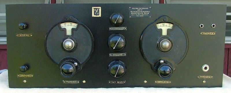
From what I gather in old ads, Mr. Hatry and a Mr. Young teamed up and
were
producing this set on a custom order basis during 1931. It was
labelled as the HY-7 and there were various versions, including a set
using AC tubes. Hatry & Young remained as an electronics
distributor in Hartford for decades to come.
From a ham in the Hartford area, Peter Bertini K1ZJH : I actually remember the Hatry and
Young storefront on Ann Street, and but I am more familiar with the
time period when they located at High Street in Hartford.
High Street where they had a TV parts supply counter in the rear of the
store, with a front window display for ham gear. Corky, W1KXM was
the ham store manager, and was the main reason the ham section kept
going as long as it did. His becoming a SK in the 70s pretty much
marked the end of Hatry's as being a large ham supply house.. Before
the store went bankrupt in the 90s, they had moved operations to larger
"warehouse" operation in the south end of Hartford. By that time the
ham section was in a small remote corner area of the store. They
had another smaller operation in New Haven. I spent many Saturdays as a
teen in Hatrys!
I built the earlier battery-powered version using 22 and 01A tubes -
basically following the info in the June 1930 article although I had no
Crosley Bandbox which I could butcher. There are some later
versions shown schematically at Nostalgia
Air. You'll also find a late model of this set in the
reprint of the 1934
Official Short Wave Radio Manual and in the Manual
of Short Wave Radio If you back track inside that URL
you'll find the actual articles.
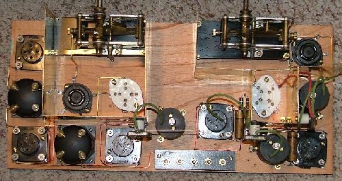
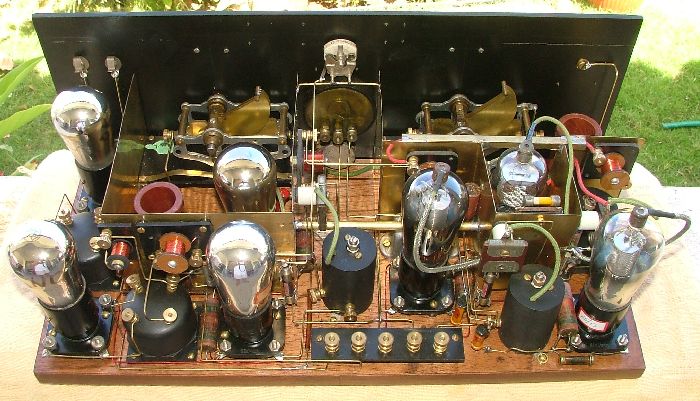
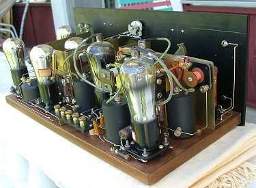
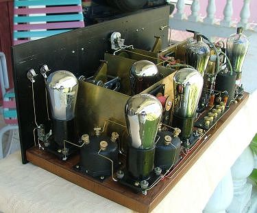
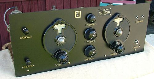
The project was laid out on an 18 by 8 inch wooden base. Thats a
bit on the small side and really packs in the components but I had
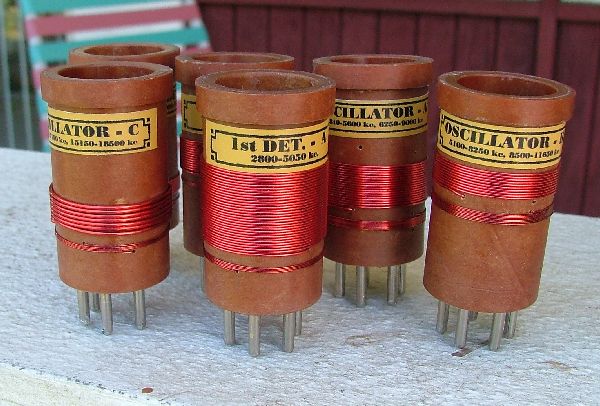
available a cabinet which I hoped to use with it. Lacking the
specific coils, etc I had to build all of them on my own and the
details are described herein.
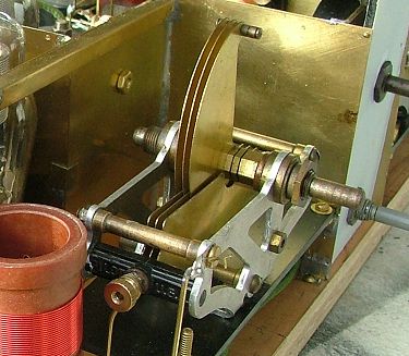
The variable capacitors I selected are Pilot Capacigrad SLF
types. I removed a few plates to bring the capacitance to about
90pf for the antenna/detector circuit and about 55 in the
oscillator. My coils were wound to match those values.
I selected 1725
kHz for an IF frequency since the original 1550 is no longer a good
choice of
IF frequency. These are the resonant IF circuits. I used an
FT-50A ferrite core, 100pf fixed cap and a 30pf trimmer.
Ceramic sockets are used for the oscillator and RF tubes, the others
are standard Benjamin type breadboard sockets.
Shielding partitions for the RF and Oscillator sections were cut from
brass stock and the bulk of the wiring was done with 3/64" brass rod
with 1/16" rod used for the tuned circuit connections (variable caps,
etc) for additional stability.
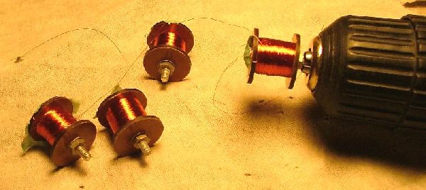
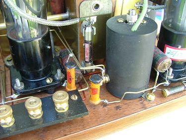
The circuit as described is very intense on decoupling between the dc
supply lines to the various stages. I used homemade chokes in the
25mH range for the plate supply lines to each stage as well as
bypassing each one individually with .15mf capacitors. Screen
lines for the 22 tubes use a decoupling resistor of about 3k and a
restuffed 0.15 capacitor as well. I used a 4.65 mH choke on the
oscillator
supply line. The chokes were wound with #36 wire, no particular
number of turns - just "a bunch" - enough to eyeball them into range
after measuring the first example.
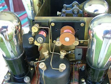
Instead of a switch to simply throw the detector in or out of
regeneration I opted to use a variable capacitor for that function.
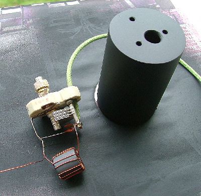
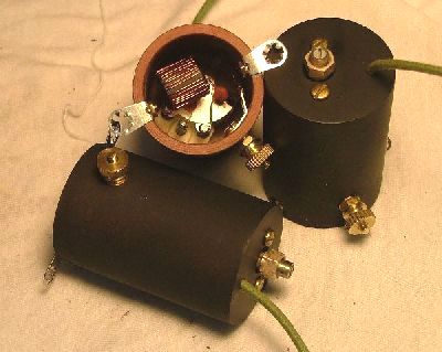
Interstage audio coupling xfmrs were made using an inexpensive 1:2
driver
transformer housed in a pvc cap which works adequately in this circuit.
The front panel is made from 3/16" garolite phenolic grade XX material
and lettered with homemade escutcheons made with decals on brass
stock. The three gridleak holders were homemade using fuse clips
because none of the old stock ones I had would easily fit in the
crowded layout.
INITIAL TESTS:
I always love firing up a radio for the first time and hearing the
squeals and squawks that indicate that its doing something! This
one indeed made a racket when first turned on.
First problem I encountered was that my IF coil calculations were way
too low and I was down in the BCB and could not move up sufficiently to
avoid BCB interference. I removed 3 turns on my coils and that
got me up to the desired 1700-25 range and its worth noting that these
coils
peak rather sharply with the components I used and there's only about
100-125 kc of range with the trimmers used. Although I had fudged
in a bit for circuit stray capacitance it wasn't enough. I
measured close to 30 pf with tubes in place.
The next obvious need was for shielded wire on the grids of the 2 IF
amp tubes. Getting a hand within inches of the wire leads
provoked
undesired "results", Adding a grounded braid shield to the wire
eliminated that entirely. The mixer tube didn't seem to be
bothered by this erratic behaviour. Adding the braid seemed to
throw in a tad more capacitance to the circuit so I moved the IF down
to 1700. Thats ok in this location since I have no strong signals
above 1620.
Regeneration seemed tight and distinct with that desirable 'click'
. I used a ~35pf variable cap in the IFs and since the regen
remains at the
IF freq there's no significant variance to speak of. The variable
is still desirable because it gives a bit more control of the set
although the original circuit simply uses a switch to throw it in or
out of regeneration. There remain enough variances when adjusting
the other pots to where a light tweak of the Regen control is desirable.
Although the texts compare the mixing scheme
to the Ultradyne space charge mixer and there's really not much
similarity. Its a tetrode with signal injection on the screen
and LO injection on the control grid and full B+ on the plate. I
was presented
with terrible distortion on mixed signals, while an IF signal passed
thru quite cleanly. It turns out that it was a self-imposed
problem. The power supply I'm using has a common B-/A+ internal
connection and reversing the A leads cured it. Since I had the
o'scope out for troubleshooting I took the opportunity to trace a
signal straight to the 2nd detector. It remained VERY
clean. I also noted that my 01A oscillator was as clean if not
cleaner than my signal generator :) As a note, I had 1.4 v p-p
injection at the grid with 32 volts B+ on the osc. There's about
+5 or 6 volts dc on the grid as well. I'm not sure what to make
of that but it seems to work ok. I did try the more conventional
method of injecting the rf on the control grid and LO onto the screen
and it indeed seems to work better when done in the manner prescribed
by Mr. Hatry although you rarely see this done in other sets. The
setting of the 500k Bias Pot is also fairly critical. Again,
I'm not sure why this is but it seems critical within a volt or so
where the mixer works...or doesn't.
ON-AIR TESTING
I wasn't really sure what to expect out of a shortwave superhet of the
~1929 era. I was pleasantly surprised to see the old 01A
oscillating well past 18 Mhz although its not really very stable for
SSB use. With the high IF, and decent selectivity at the front
end images are not an issue. In fact the coil scheme allows for
different tuning ranges by simply selecting the upper or lower IF
product in conjunction with the appropriate detector coil. My set
of coils covers from about 2850 kc to 16500 kc.
"
Riding" the Volume Control because of no AVC is mandatory and listening
to a rapidly fading SW signal can be rough on the ears.
Selectivity is plenty adequate with the 3 tuned IF circuits and
regeneration.
This was a fun project to built and quite a challenge. Its a very
respectable shortwave receiver and somewhat better than I had expected
using late 1920s technology. These old circuits are full of
surprises!