A Tuned Plate - Tuned Grid
TPTG Receiver
Homebrew
Regenerative Shortwave Receiver
This set has a bit of historical
interest because its not so distant from one of EH Armstrong's original
patent designs ca 1913-14. You can download the original USA
patent
(1,113,149) and its diagrams here.
The Armstrong designs were focused on the frequency range of
several
thousand meters and did things like using the earpiece coil as the
tuned inductance so they don't immediately reveal themselves as the
predecessors of the later sets. But its the regeneration
technique that was of interest and if you review the patent its clear
that Mr. Armstrong found several ways to skin the proverbial cat.
Billy Richardson sent me the following additional information on the
development of this circuit along with the Jones article:
This circuit goes back to about 1915,
when the capacity between the elements of the tube was fairly
high. Tuning the plate did not add to this capacity, so
regeneration could be used to tune 200 meters. Prior to this
development, 200 meters was almost a useless band. Later tubes
had less capacity between the elements, so they could easily tune that
frequency, even with a tickler winding. When the hams began
working at even higher frequencies in the mid 20's, the same old
problem began happening, so the tuned plate once again allowed them to
coax a little more from the available tubes.
The circuit that Paul Godley came up
with in about 1915 tuned the plate with a variometer. A good many
of the hams continued to use this method well into the 20's, but it was
a bit crude on the newer frequencies. That's when some of them
began replacing it with a fixed coil and a tuning condenser.
The circuit saw some commercial use in the early 1920s, the
Atwater-Kent Model 1 is a typical example that used a variometer to
tune the plate.
Fast forward ten years to an article in January
1926 RADIO magazine by
Frank C. Jones taking this circuit to the shortwave spectrum.
By
this time the TPTG circuit had become popularized as a TRANSMITTING
power oscillator, even on the HF bands. My guess is that Jones
saw this as a possibility to review its use as a regenerative detector
at high frequencies. My set is built based on his article.
The article itself is short on construction details but most of it is
easy to figure out. What is amazing is that he claimed it
provided good service as high as 5-6 meters. My version didn't
turn out that way, however.
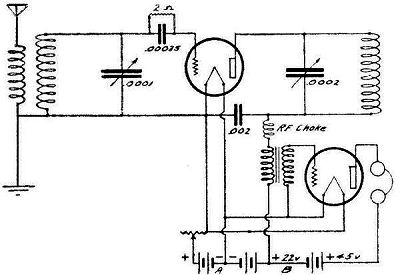
Nothing really bizarre here. Instead of today's more
common
tickler configuration, the plate circuit is tuned 'close' to resonance
and allowed to feed
back via the tube's internal capacitance encouraging oscillation.
This is a condition known by anybody who has worked with triode
RF amplifiers because it often takes neutralization to prevent
it! The
trick in a receiving detector is how to manage it for usefulness.
To get a decent tuning ratio and to cover a wider frequency range plug
in coils are required. The article is a bit misleading in
that it used two variable caps, one of which was butchered down to 3
plates and increasing the spacing. My guess was that probably
resulted in 30pf or so as a tuning cap although the schematic shows
.0001 (100pf). I started with about 50pf and it became quickly
apparent that I would need a boxful of coils for general
coverage. I was shooting for ~3-12 Mcs. 30 or 50 pf would
be a good number for a ham-band only receiver, or 5-6 meter
receiver. I put back my plates and settled on a cap of about
85pf. That gives me great overlapping coverage with 4 grid coils
that presumably would carry me up above 15 Mc.
The plate capacitor is not so critical in tuning and is a 200pf
unit. In this example it only takes 3 coils to cover well beyond
20 Mcs. In case its not obvious, the plate cap serves as the
regeneration control as it is tuned closer to the grid frequency.
Its easy to see why some of the TPTG xmtrs of the era weren't
particularly stable. Two tuned circuits are here and they both
need to be of adequate Q and stability.
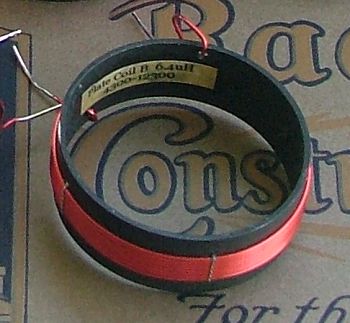
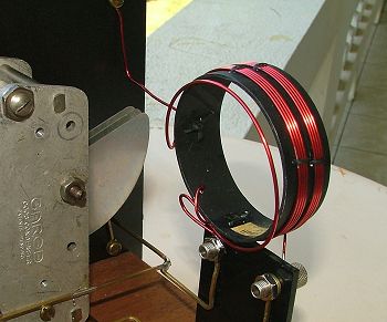
Here's how I did my coils. This is a piece of PVC painted black
about 2.5" in diameter. The coils are wound with #16 and #18 wire
and held tight with lacing cord. The right hand photo shows the
antenna coupling which is simply a 3/4 turn loop placed close to the
grid coil.
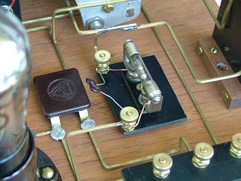
In the course of building this thing I ran into a
perplexing
problem
that was very time-consuming to figure out, or rather, stumble onto a
solution. It didn't seem to want to oscillate beyond 8 Mcs no
matter what I did. I tried different coil configurations, etc,
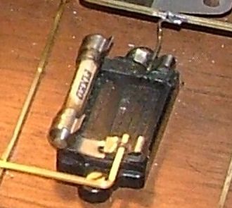
but it still died out promptly close to 8 Megs. The culprit
turned out to be the little molded mica cap with gridleak holder.
Fresh out of the box, NOS. I had disconnected one end while I was
experimenting with different grid R and C values so I really didn't
give it much thought but as it turned out it was terribly leaky, in
fact just a megohm or two between its terminal and my wood base!
After getting it completely out of the circuit the old 01A zoomed right
up towards 14-15 Mcs. Here's the original style and my
'improved' version. With it I can juggle to grid resistor and cap
values for best performance. My plate RF choke is handwound,
about 3mH.
I might mention also that I have done some hand-picking of
01As.
My best tube will get me up into the 20 meter band but its on the testy
edge by then. Some of the other tubes are crapping out as low as
9.5 Mcs. That said, plan on having a very good tube if you want
to go this high in frequency. I imagine that beyond that my
limitations are basically due to wiring and layout issues. It
would take a bold and clever constructor, and maybe a bit of voodoo to
get this thing up to 50 Mcs.
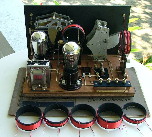
Here's a rear view that shows the wiring of the receiver. I
allowed terminals on the front panel for connection to a Two-Step Audio
Amplifier that I previously built but quite frankly this receiver with
its one
stage of audio is more than adequate on its own for headphone listening.
Performance? I'm very pleased. I really didn't expect
to
hear anything at night on the 25-meter SW band but after tweaking the
grid leak I found it full of stations. I
settled on 10 Megohms and
68pf, by the way. I lost regeneration with lower capacitance
values and at 2-4 Megs for a grid leak it wasn't performing very well
on the upper frequencies. Same story on 31 meters,
more stations than I could log
or count easily in an evening's session. 40 meters!
WoW! A CW contest was going on and I had to drop the audio amp B+
voltage down to 17-18 (thats where the detector is running) for
comfortable listening. (I have since gone to a larger filament
rheostat for
that stage). The rcvr is plenty stable enough for casual ham
operation. Same story on 49 and 60 meters. I'm starting to
get some of that regen 'buzz' at the lower frequencies so there's still
tweaking to do.
Its definitely a 2-handed rig. The plate tuning
(regeneration) needs constant tweaking as you make moves in
frequency. Once the set was trimmed out...and the 'fringe howl'
eliminated...it tunes very smoothly and although excursions of 5-10 kc
require readjustment there's still some degree of play if you are not
trying to peak every signal for max. Even with the small knob and
no vernier its not too terrible to adjust. There's some slight
frequency shifting as the plate adjustment is tuned, this can be
annoying on a crowded CW band. I used separate rheostats for the
two stages and the detector rheostat seems best left set to about
3.5-4.0 volts. You can get a bit of regeneration fine tuning with
that control as well and that helps on CW.
I'd hate to build a rig like this
from scratch without the aid of a grid-dip meter or at least a decent
LC meter to get a rough calibration of the two tuned circuits. It
will do some strange things resulting in all sorts of birdies and spurs
when it is mistuned. When you hit the correct tuning, though, its
very obvious that you are in the right spot. With a TPTG Receiver
you can hear the result...with the old TPTG Transmitters you never know
what may have been going out!
...
26 November 2006
